3 Key Competencies in Solidworks

I remember the day I was a junior intern at an office, and I asked to help with CAD. I knew how to use Rhino, and I thought I knew how to use Solidworks. They gave me the simplest part of the design, the reservoir dish of a medical machine. Looking back, this was such a straightforward piece. The design director came around and saw I had accomplished the task, then said, “Change this diameter.” As soon as I did, my entire history turned red and yellow. He looked at the senior designer next to me and said, “You do it!” Fast forward a few years, and I had made it my mission to master this software. Since then, I have been teaching it at two major design schools in New York.
Nowadays, building geometry in the computer can be accomplished by at least a hundred software and apps. If you or the company you work for chose Solidworks, it’s likely for two main reasons: it’s designed to constrain you to build precise, ready-to-manufacture products, and its parametric capabilities make it very efficient when working in a team on projects that require a lot of changes and testing. Solidworks is a very robust tool, and most likely in your career as a designer, you will use only 20% of what it can do, which is still a lot. After ten years dedicated to teaching the tool, here are my recommendations to master this tool.
Master the art of sketching and defining sketches
This sounds simple, but so many times I’ve encountered a file where the drawing is miles away from the origin, the lines are all blue, and there are no parametric constraints. So how do you get sketching right?
- Firstly, all points need to have a defined (x,y) coordinate. You can achieve this through a smart dimension, a relationship to the origin or another point, and/or a relationship to existing geometry. By defining one part of your design to the origin and building strong and rational relationships on top of it, you will avoid worrying about this as you design.
2. Secondly, all lines need a defined length and angle. Whether you define this through a dimension or a relationship, you should know the dimensions of every part of your design. I don’t understand when I see dimensions like 1.3647 — why not round up or down and have control over the design?
3. Next, keep your sketches simple. The more points you have, the more relationships and definitions you will need to control them. When you do surfacing, the more points the more variations your surface will have. If using splines, a two-point or three-point spline will usually suffice; the more points you have, the messier things will become.
4. Avoid using the fillet tool unless you need to. I prefer using the Fillet feature because it offers me editability and keeps my sketch simple.
5. Lastly, use convert entities and offset when possible. This will automatically build a parametric relationship that will help you edit your design without having to edit and change each feature.
That’s it! Practice these guidelines in all your sketches, and I promise you will save yourself 30% of your time in each model.

Create Smart Workflows
- Design your product in a single part file, and then extract its components into independent part files that you can use for prototyping or testing in an assembly. This approach allows you to reference multiple components that come together, and easily add tolerances and fitting features. It also keeps your files organized during the design process and can help prevent SolidWorks from crashing due to memory constraints or errors with references.
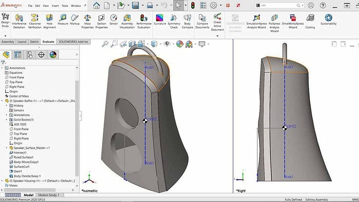
- Use “Master Sketches” to control the scale, proportions, and details of your design elements in a single location. This enables you to make major changes quickly and easily.
- Keep your part files and component names organized so that when you export them for an assembly or technical drawing, they match up correctly. This will save you time and prevent confusion when working on complex designs.
- Use configurations to manage variations of a part or assembly. This can save time and make it easier to switch between different versions of the same design without creating new files from scratch.
- Take advantage of the Design Library to store frequently used features, parts, and assemblies. This can save you time by allowing you to quickly access these components and reuse them in multiple designs.

Build Parametric Geometry
Wait, isn’t everything in Solidworks parametric since it is parametric software? No, you have to create relationships between the elements in your design to make this happen. So how do you do it?
- Use relationships in all major features to define your Z-axis. For example, you can define an extrusion using “Up to Surface,” “Offset from Surface,” “Up to Vertex,” “Upto Next,” “Upto Body,” and more.
- Take advantage of symmetry planes. If your design is symmetrical, there’s no need to model the entire object. You can divide it in half, quarters, or even eighths if possible.
- Sketch on faces whenever possible. Rather than building new planes or creating forms from a different view, use every flat face available so that your next feature is immediately connected.
- Utilize equations and global variables to drive your design. This allows you to make changes in one place and have it updated throughout the entire model. For instance, instead of specifying the diameter of each hole individually, you can create a global variable for the hole diameter and use that variable to drive the size of all the holes in your model. This makes it much easier to modify your design later on.
- Use configurations to create variations of your design. Configurations enable you to make multiple versions of your model within a single file. This is useful if you need different versions of your design for different purposes, such as different sizes or materials. By using these techniques, you can establish strong parametric relationships in your Solidworks models, making them easier to modify and update as necessary.

Conclusions
Learning Solidworks, or any other CAD software, is essential for anyone interested in becoming a professional designer. The ability to sketch and define sketches accurately, create smart workflows, and build parametric geometry is crucial for producing precise, ready-to-manufacture products and collaborating efficiently in a team. The recommendations outlined in this article provide a foundation for mastering Solidworks and becoming a successful designer. With these guidelines, designers can increase their productivity, save time, and prevent costly mistakes. As such, it is essential to learn Solidworks to empower oneself to collaborate with other people and build for production.
If you are starting up with Solidworks I invite you to check my Lemanoosh course (https://courses.lemanoosh.com/a/2147854400/3sk4JzPF) where we cover the basic tools and great strategies to master this program.
Like my Article?
Follow me for more articles about design.
If you enjoyed this post, please show some appreciation by clicking on the “clap” button. Did you know — you can hit it up to 50 times? It helps the content reach out to more people like you who might benefit from reading it.
Feel free to drop a message on LinkedIn or by Email for any questions, feedback, and suggestions. This will help me improve and also inspire me to create more.
